Why This CO2 Sequestration Project Matters
As carbon capture and storage (CCS) accelerates worldwide, operators face a critical challenge: how to reliably image, monitor, and predict the behavior of CO₂ underground.
SEAM’s CO₂ Sequestration Project gives industry, academia, and government collaborators a unique opportunity to test 4D geophysical approaches, evaluate acquisition strategies, and refine interpretation workflows using some of the most advanced CCS models ever constructed.
This is where CCS uncertainty becomes CCS insight—before entering the field.
Be Part of the Same R&D Community as the Industry’s Most Influential Operators.
SEAM participants represent decades of subsurface leadership, innovation, and strategic investment. Companies that join SEAM gain early access to new data, shape project direction, and collaborate with world-class experts.


Join the R&D ecosystem trusted by global energy leaders
The SEG Advanced Modeling Corporation (SEAM) is the research arm of SEG.
We bring together energy companies, researchers, and government partners to tackle the toughest subsurface challenges.
Introduction
The models will be allowed to evolve in time as CO2 is injected into the subsurface reservoir and migrates within the subsurface in either a contained reservoir or one that does not contain the injected fluid. Geophysical models will be constructed from the temporal sequence of reservoir states during fluid injection. Geophysical simulation will be conducted on the models to help to evaluate the 4D geophysical response of the subsurface. The simulated data will be used to construct images of the earth’s subsurface, which can then be interpreted to infer the state of the reservoir, the locations of CO2 and the reliability of the reservoir seal.
Such an interpretation could allow project participants to evaluate the benefits of the various geophysical acquisition and processing approaches for characterizing reservoirs undergoing CO2 injection and sequestration.
The SEAM CO2 model is meant to be representative of a class of reservoirs where CO2 may be injected for sequestration. It does not represent any real-world reservoir.

SEAM in the News
SEAM Update: SEAM CO2 project: Evaluating geophysical methods for characterization of CO2 injections

Technical Specifications
Reservoir Description: The main reservoir in the ongoing model (onshore pilot) consists of a sequence of stacked turbidites located below a shale caprock. Two reservoirs exist at different depths above the caprock that are potential locations for CO2 which has migrated through the caprock by various mechanisms. A new marine model having a depleted gas reservoir is currently under construction and will involve similar simulations as were done on the onshore pilot model.
Simulations: Reservoir modeling has provided good information about the containment and/or migration of CO2 within the reservoir and through the leakage pathways. This information has led to a refinement of the model to make it more appropriate for participants’ interests.
- Coupled reservoir flow/geomechanical simulations provide the most realistic model for the distribution of CO2 within the model.
- Several scenarios have been tested and include one in which CO2 is fully contained within the main reservoir and others where CO2 leaks into the upper siliciclastic reservoirs by passing through the reservoir caprock and along a fault.
Geophysical simulations are being conducted on 4 reservoir models:
- Model 1: Baseline model prior to injection of CO2.
- Model 2: A scenario where all CO2 is contained at 30 years after the initiation of injection.
- Model 3: A scenario where CO2 migrates* above the caprock- simulation at 9 years after the start of injection.
- Model 4: A scenario where CO2 migrates* above the caprock- simulation at 30 years after the start of injection.
*CO2 migration through the shale caprock into a middle reservoir immediately above the caprock and along a fault that penetrates the reservoir and has continuity up to a shallow reservoir at 500 m where CO2 migrates.
CO2 Program Geophysical Simulation Products (Onshore pilot)
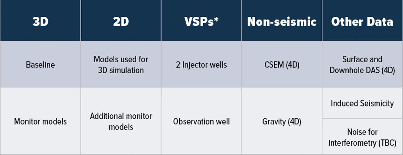
*On the same models as used for 2D seismic
3D migration imaging will be conducted on 3D seismic datasets, 2D imaging will be conducted on the 2D datasets and on the VSP data (approach TBD).
We define 2D seismic to be 3D simulations where sources and receivers all fall along lines passing through one or two wellbores. These data will be processed using 2D imaging algorithms.
4D Controlled-source EM simulations will be conducted on the baseline and at least one monitor model. 4D gravity simulations have been conducted on 3 monitor models.
Why Participate?
When you join the SEAM CO₂ Sequestration Project, you gain:
Early Access to Critical CCS Insights
Receive simulation data two years before general industry release, ensuring a competitive advantage in CCS research, planning, and deployment.
A Voice in the Science
Shape objectives, model parameters, and deliverables. SEAM projects are not passive—they’re built by the participants.
A Cost-Effective R&D Engine
Share the high costs of CCS modeling across a consortium of global leaders.
Confidence in Your CCS Strategy
Evaluate 4D seismic, EM, gravity, and VSP workflows in a controlled environment before bringing them to the field.